

HONESTY IS THE ROOT
Quality is always satisfactory
Hotline
400-606-8981
PRODUCT CATEGORY
LATEST NEWS
MORE
PRODUCT DETAILS
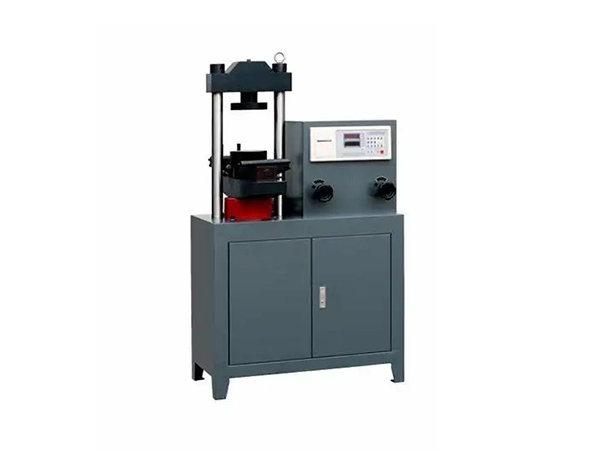
1、 The DYE-300 digital flexural and compressive testing machine is mainly used for testing the flexural strength of 100X100X400 (mm) and 150X150X550 (mm) concrete tests, as well as the compressive strength of building materials such as cement and mortar
2、 This testing machine is an electric hydraulic type, with sensors measuring force and digital display of force values. It is a testing and inspection equipment required by construction, building materials, highways, bridges and other engineering units
3、 This testing machine complies with GB/T50081-2002 "Test Methods for Mechanical Properties of Ordinary Concrete", and should be manually controlled for loading speed. It should also have a loading speed indicator device, which can uniformly and continuously load during the test process. It should also be equipped with a bending test device that can make two equal loads act simultaneously at the three-point of the specimen span
4、 According to the national standard GB/T5008-2002 "Test Method for Mechanical Properties of Ordinary Concrete", during the testing process, when the specimen is close to failure, the adjustment of the test oil valve should be stopped until the specimen is damaged, and then the failure load value and the fracture position of the lower edge of the specimen should be recorded
2. Main specifications and technical parameters
1. Large load: 300KN
2. Accuracy level: Main product
3. Force measurement range: 30-300KN
4. Small resolution: 0.1KN
5. Instrument voltage: 220V ± 10%
6. Motor voltage: 380V ± 10%
7. Motor power: 0.75KW
8. Relative error of indication: ± 1%
9. High oil pressure: 25MPa
10. Resistance Diameter of the folding roller: Φ30mm
11、 Vertical spacing between anti bending rollers (clear distance): Φ165mm
12、 Center distance between upper anti bending rollers: 150mm
13. Center distance between lower anti bending rollers: 450mm
14. Pressure plate diameter: Φ160mm
15、 Clear distance between upper and lower pressure plates: 180mm
16. Piston diameter X larger stroke: Φ125X100mm
17、 Dimensions: 840X530X1450mm
18. Net weight: 400Kg
III. Main structure and working principle
The testing machine is mainly composed of a bracket, hydraulic control box, instrument force display, and electrical system
1、 Body parts: The testing machine body has a measuring column, upper and lower anti bending device, cylinder body, frame, bottom plate, and measuring instrument installed on the upper right side of the frame. The hydraulic operation part is installed on the lower right side of the frame. The lower anti bending device is installed on the top of the piston, and guide plates are installed on both sides to maintain the up and down movement position of the anti bending table. A ruler is installed on the anti bending table, and two guide plates are installed on both sides. The anti bending span can be adjusted arbitrarily. The towing roller can move up and down to balance under force. The upper anti bending device is installed under the measuring column, and is fixed under the crossbeam with two positioning columns through U-bolts. There are ball heads and ball seats during the process, and springs are installed on the bolts to balance the upper anti bending device. The roller can move up and down, and during the bending test, it can automatically adjust its position according to the surface condition of the specimen, Align the curved surface of the indenter with the specimen to ensure the accuracy of the test. On the oil cylinder and the plane, dust rings are installed to prevent or reduce dust from entering between the piston and the oil cylinder when the piston rises and falls, which accelerates their wear. When resisting pressure, as long as a compression pad and a lower pressure plate are placed in the middle of the anti bending table, and the anti bending device is removed under the crossbeam, the compression test can be carried out. There is a sealing ring between the piston and the oil cylinder to prevent oil leakage. There is an annular groove on the top of the cylinder and an oil leakage channel, which allows the oil to overflow back to the oil tank through a plastic pipe
2、 Hydraulic control part
The control box of this testing machine mainly includes a mailbox, a hydraulic oil filter, an electric motor, a speed valve, a return valve, and an open oil delivery valve. The piston slowly rises
3、 Detailed reading of force measuring instruments (instrument manual)
4. Electrical system
It consists of an electric motor, a start button, a stop button, an AC contactor, etc
IV. Installation and Debugging of Testing Machine
The installation foundation of this testing machine should be firm and excellent, suitable for operation and ensure correct readings. The foundation can be appropriately raised above the ground, and the height should be determined according to actual needs. A space of not less than 0.7m should be left around the testing machine for maintenance and operation. The anchor 2 bolts (M12X300mm) should be grouted twice to confirm that the bolts are buried correctly and installed to maintain the level of the testing machine (level less than or equal to 0.1/1000). A 0.1/1000 frame level should be used to measure the plane of the anti bending table surface. If the horizontal or vertical level exceeds the regulations, a shim can be added to the bottom plate for correction, and then the anchor bolts should be tightened and the power line connected. The electrical system of this machine There should be a grounding safety protection device, and the voltage variation of the power supply should not exceed 10% of the rated value
Fifth, Use and Operation
1. Preparation and Inspection Before Use
Before use, open the rear door and check if the hydraulic oil in the mailbox is full. If it is not full, fill the oil tank with oil until it is full. Check if the oil pipe joints and fasteners are loose. If they are loose, tighten them to prevent oil leakage or damage to the parts, affecting the test. Check if the dust ring is intact and undamaged, check if the electrical grounding and safety protection measures are effective, check if there are obvious defects in the appearance of the test piece, wipe the surface of the test piece clean, and if it affects the test value, replace the undamaged test piece.
2、 Operating procedures, methods, and precautions
At the beginning, turn the left oil return valve to the open position and the right oil delivery valve to the slow position. Press the start button to turn on the power, and the oil pump motor starts to run. Rotate the oil return valve handle clockwise to the fully closed position, and then slowly open the oil delivery valve to raise the piston a certain distance. Observe whether there is any jamming or other phenomenon. If there is any abnormal phenomenon, stop the machine for inspection and eliminate it. If there is no abnormal phenomenon, then check whether there is a zero point on the next instrument display screen. If there is a number, press the reset button to modulate the zero position, and then open the oil return valve to lower the piston to its original position
During the anti bending process, according to the markings on the ruler and the specifications of the specimen, place the specimen flat on the support roller of the lower anti bending device, then close the oil return valve and turn the oil delivery valve to make the specimen rise quickly before coming into contact with the upper anti bending device to save test time. When it comes into contact with the upper anti bending device, slowly raise the piston until it breaks, then close the oil delivery valve to stop the piston from rising, and open the oil return valve counterclockwise. The piston will then descend to its original position by its own weight. At this time, observe and record the value displayed on the instrument, which is the larger anti bending force of the specimen obtained. Then cancel the broken piece and press the reset button for the next testWhen compressing, place the specimen flat at the center of the lower pressure plate, turn the oil feeding valve to make the specimen rise quickly before coming into contact with the upper pressure plate to save test time. When it comes into contact with the upper pressure plate, slowly raise the piston until the specimen is crushed. Close the oil feeding valve, open the oil return valve, and record the force value data. Then, clearly break the specimen and press the reset button to wait for another testDuring operation, it is forbidden to place hands or any other part of the human body between the upper and lower pressure plates, and attention should be paid to the possibility of the specimen breaking and causing injury. After the specimen breaks, the return valve should be opened immediately, but the speed of opening the return valve should not be too fast, otherwise it may damage the parts and cause unnecessary losses6. Maintenance: 1. The testing machine should be installed in a clean, dry, uniform temperature, vibration free environment, and free from corrosive gases
2、 The testing machine should be kept clean, and parts without protective layers should be regularly wiped with oil to prevent rust
3、 After using the testing machine for six months to a year, the oil should be changed once. When changing the oil, the oil tank, oil filter, and oil tank should be thoroughly cleaned. The method of cleaning the oil tank can be to fill the tank with kerosene, clean it, and then release it. Repeat this process several times until it is clean, and wipe the bottom of the tank with a towel before adding clean hydraulic oil. If the hydraulic oil is found to be severely turbid and cannot be used anymore, it should be replaced immediately, otherwise it will accelerate the wear of various hydraulic components and even affect the accuracy of the value
Hydraulic oil specifications vary depending on the temperature.
(1) When the ambient temperature is 10-20 ° C, use GB-443-84N46 #
(2) When the ambient temperature is 20-30 ° C, use GB-443-84N48 #
4. When not in use, the machine should be covered with plastic
7. Calibration of the testing machine
1. This testing machine should be calibrated once a year
2. The calibration of the testing machine should be carried out under the following conditions
(1) Within the range of 20 ± 10 ° C at room temperature
(2) In an environment with a relative humidity of ≤ 80%(3) In a vibration free environment(4) The fluctuation of the power supply voltage does not exceed ± 10% of the fixed voltage, and the voltage is relatively stable
3、 Start the motor, repeat the loading process three times until a larger load is reached. After unloading, press the instrument reset button to adjust the instrument display to zero position and begin calibration
4、 This testing machine only performs calibration of relative error and relative variability of indication. The calibrated results should reach:
Relative error of indication: ≤ 1%
Relative variability of indication: ≤ ± 1%
Mainly used for flexural strength testing of concrete specimens and compressive strength testing of building materials such as cement, mortar, and red bricks. Adopting hydraulic loading and electronic force measurement, it has functions such as load digital display, loading rate display, large load value display, as well as overload protection and power-off data retention